
Views: 209 Author: Reshine Publish Time: 2023-07-05 Origin: Site


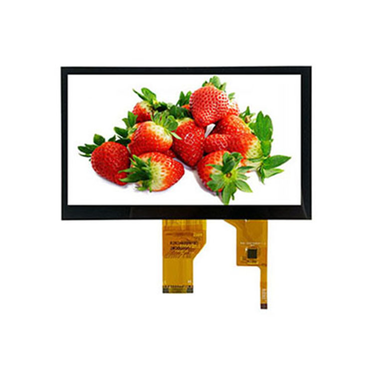
A TFT (Thin Film Transistor) is a thin film field-effect transistor. The so-called thin film transistor means that each liquid crystal pixel point on the LCD is driven by a thin film transistor integrated into the back. TFT is an active matrix liquid crystal display. The composition of an LCD is not complicated. The LCD board plus the corresponding driver board (also known as the main board; note that the LCD panel is not within the ranks of the driver circuit), power supply board, high voltage board, button control board, etc., constitutes a complete LCD monitor. Related Product: TFT LCD display.
The power supply circuit of an LCD is divided into two parts: the switching power supply and the DC/DC converter.
The driver board, also known as the main board, is the core circuit of the LCD, mainly composed of the following parts:
LCD monitors are generally equipped with a VGA interface (D-Sub interface) to transmit analog signals and a DVI interface to transmit digital signals. Among them, the VGA interface is used to receive the analog R, G, B, and line field synchronization signals output from the host graphics card; the DVI interface is used to receive the TMDS data and clock signals output from the TMDS (Minimized Transmission Differential Signal) transmitter of the host graphics card, and the received TMDS signals need to be decoded by the TMDS receiver inside the LCD to be added to the Sealer circuit, however. Many TMDS receivers are integrated into the Scaler chip.
The A/D converter circuit is an analog-to-digital converter that converts the analog R, G, and B signals from the VGA interface into digital signals, which are then sent to the Sealer circuit for processing. In the early days of LCD, an A/D converter chip (such as AD9883, AD9884, etc.) was usually set up separately, but in the production of LCD, most of the A/D converter circuits have been integrated into the Scaler chip.
The clock generator circuit receives line synchronization, field synchronization, and an external crystal clock signal and generates a clock signal, which is sent to the A/D converter circuit as a sampling clock signal on one hand; on the other hand, sent to the sealer circuit for processing to generate a pixel clock for driving the LCD screen. In addition, the coordination of the various modules within the LCD also requires the cooperation of the clock signal. The clock generator of the display is generally controlled by a phase-locked loop circuit (PLL) to improve the stability of the clock. In early LCD, the clock generator was generally integrated into the A/D conversion circuit, In the production of LCD monitors today, most of the clock generators are integrated into the Sealer chip.
Sealer circuit has more names, image scaling circuits, master control circuit, image controller, etc. The core of the Sealer circuit is a large-scale integrated circuit, called the Sealer chip, whose role is to A/D conversion of the digital signal or TMDS receiver output data and clock signal, scaling, picture quality enhancement, and other processing, and then sent to the LCD panel by the output interface circuit. The performance of the Sealer chip determines the limit of signal processing capability. In addition, there is usually a screen display circuit (0SD circuit) integrated into the Sealer circuit.
Why does the LCD need to scale the signal? This is because the pixel position and resolution of a panel are fixed after manufacturing, but the output resolution of the audio/video device is multiple. When the LCD panel has to receive different resolutions of audio/video signals, it has to be scaled to fit the size of a screen, so the signal needs to be scaled by the Sealer chip.
The microcontroller circuit mainly includes MCU (microcontroller), memory, etc. Among them, MCU is used to control and process the display key information (such as brightness adjustment, position adjustment, etc.) and the status control information of the display itself (such as no input signal identification, power-on self-test, various power-saving energy-saving mode conversion, etc.) to complete the specified functional operation. The memory (here refers to the serial EEPROM memory) is used to store the equipment data and the data required for the operation of the LCD, mainly including the basic parameters of the equipment, manufacturer, product model, resolution data, maximum line frequency, field refresh rate, etc., and also includes some data for each operation state, such as white balance data, brightness, contrast, various geometric distortion parameters, energy-saving state control data, etc., etc. Many LCDs integrate memory and MCU, and some LCDs even integrate MCU and memory in the Scaler chip. Therefore, the memory and MCU are not visible on the driver board of these LCDs.
The driver board and the LCD panel interface circuit have a variety of commonly used mainly the following three:
The first is the parallel bus TTL interface, used to drive the TTL LCD. According to the different panel resolutions, the 17L interface is divided into 48-bit or 24-bit parallel digital display signals.
The second interface is the very popular low-voltage differential LVDS interface, which is used to drive LVDS LCDs. Compared to the 17L interface, the serial interface has a higher transmission rate, lower electromagnetic radiation, and electromagnetic interference, and requires much fewer data transmission lines than the parallel interface, so the LVDS interface is better than 1TL from both a technical and cost perspective. It should be noted that for LCDs with an LVDS interface, an LVDS transmitter chip (some may be integrated into the Sealer chip) is generally required on the motherboard, and an LVDS receiver is required in the LCD panel.
The third is the RSDS (low amplitude signal) interface, which is used to drive the RSDS LCD. The RSDS interface can greatly reduce the radiation intensity and produce a healthier and more environmentally friendly crystal and can enhance EMI immunity, making the picture quality clearer and more stable.
The key circuit is installed on the key control board, in addition, the indicator is also generally installed on the key control board. When the switch is pressed, the key electronic switch is turned on; when the hand is released, the key electronic switch is turned off. The switch signal output from the key switch is sent to the MCU on the driver board, and the MCU identifies and outputs the control signal to control the relevant circuit to complete the corresponding operation and action.
The high-voltage board is commonly known as a high-voltage strip (because the board is generally long, in the form of a strip), sometimes also known as the inverter circuit or inverter, its role is to transform the low-voltage DC voltage output from the power supply into the high-frequency 600V or more high-voltage alternating current required by the LCD panel (Panel) to light up the backlight on the LCD panel. The high-voltage board mainly has two forms of installation: ① a dedicated circuit board; ② and a switching power supply circuit installed together (switching power supply using the in-circuit type).
The LCD panel is the core component of the LCD, which mainly contains the LCD, LVDS receiver (optional, LVDS LCD has this circuit), driver IC circuit (including source driver IC and gate driver IC), timing control IC (TC0N) and backlight source.


